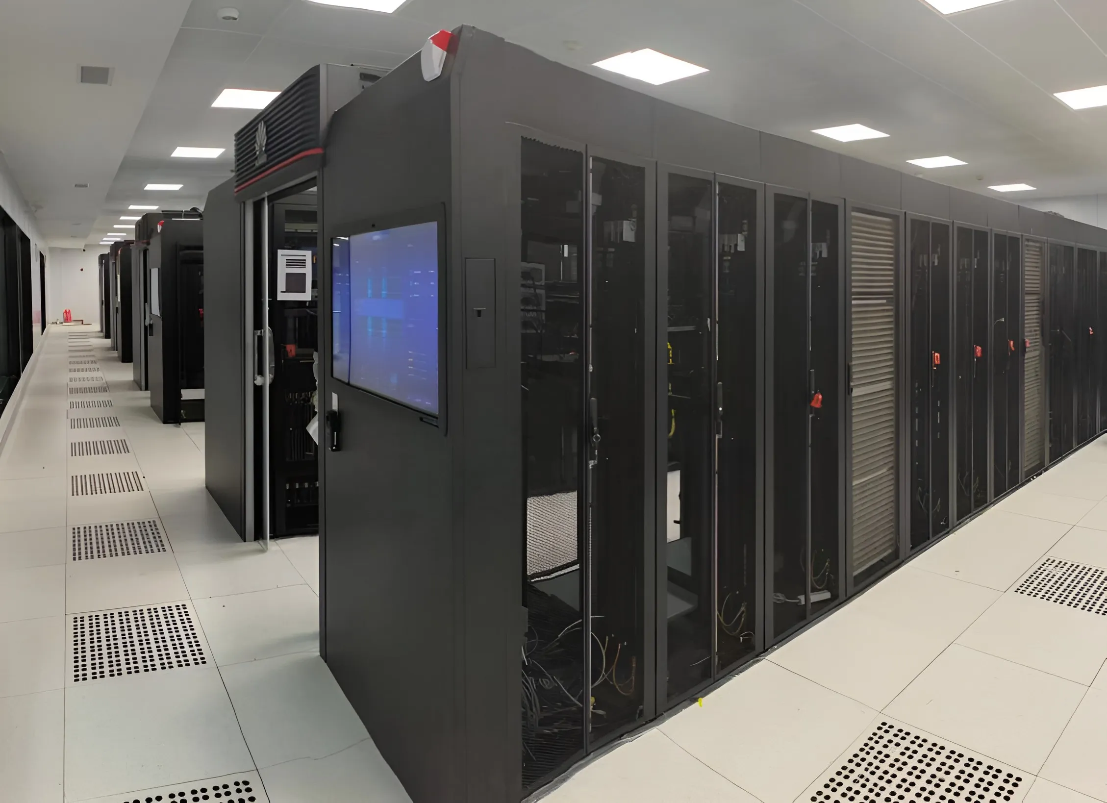
AI Data Centers
- Challenge
- GPU racks reject more heat than air can remove, and the load swings with every training run.
- Response
- Direct-to-chip loops served by centralized CDUs, with variable-speed pumping that follows the load.
Liquid cooling infrastructure
From rack-level CDUs to multi-megawatt cooling infrastructure, LINKWAVE engineers integrated thermal systems for AI, HPC and next-generation data centers.
* Across the full liquid-cooling portfolio, including power-electronics and energy applications as well as data centers.
System architecture
IT loop
01 / 09 · Heat source
By others
Processor heat flux sets every downstream requirement: coolant supply temperature, flow per server and allowable pressure drop.
02 / 09 · Chip-to-liquid heat transfer
Interface
Coolant passes through a plate mounted on the processor. Its flow and pressure-drop figures are the design inputs for the manifold and CDU.
03 / 09 · In-rack distribution
LINKWAVE scope
A stainless manifold in each rack divides supply flow between servers and collects the return through 12 mm EPDM hoses.
View productSecondary loop
04 / 09 · Local coolant distribution
LINKWAVE scope
Where load is distributed or facility water is unavailable, a CDU at the rack or row conditions and circulates coolant close to the IT equipment.
05 / 09 · Technology cooling system
LINKWAVE scope
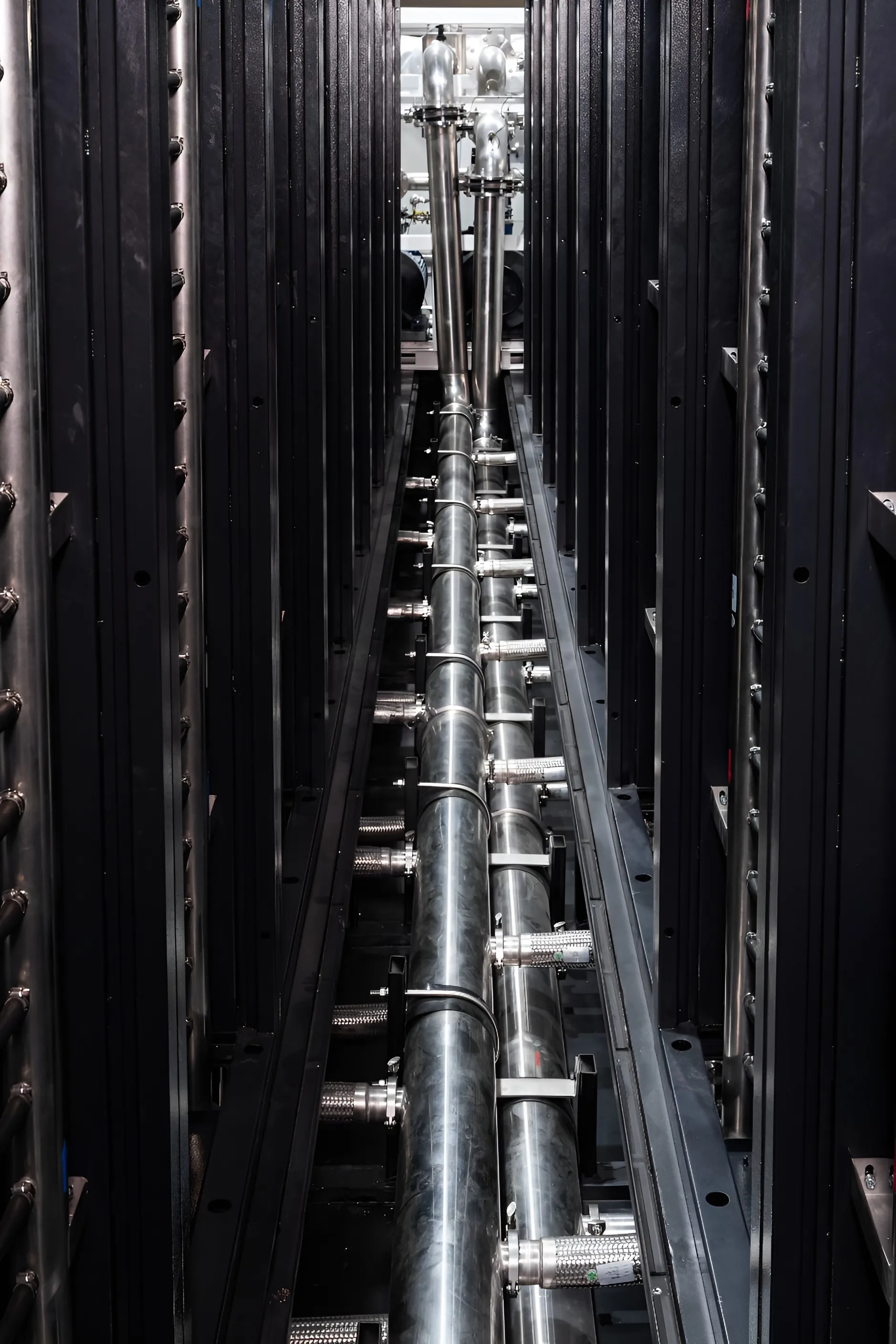
Sanitary-grade stainless aisle piping carries treated water between the racks and the CDU. Typical supply and return: 40 / 55 °C.
View product06 / 09 · Loop isolation and control
LINKWAVE scope
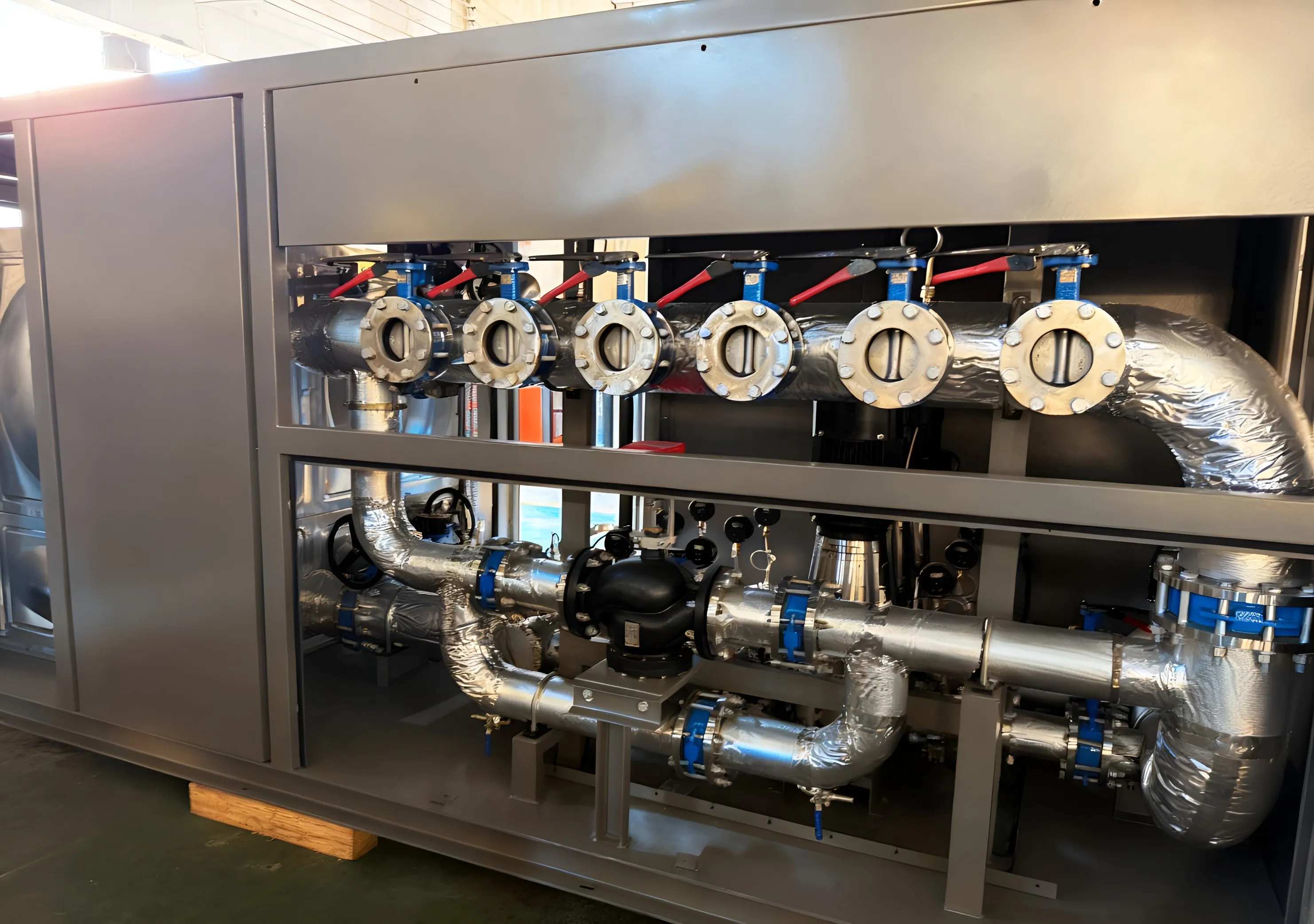
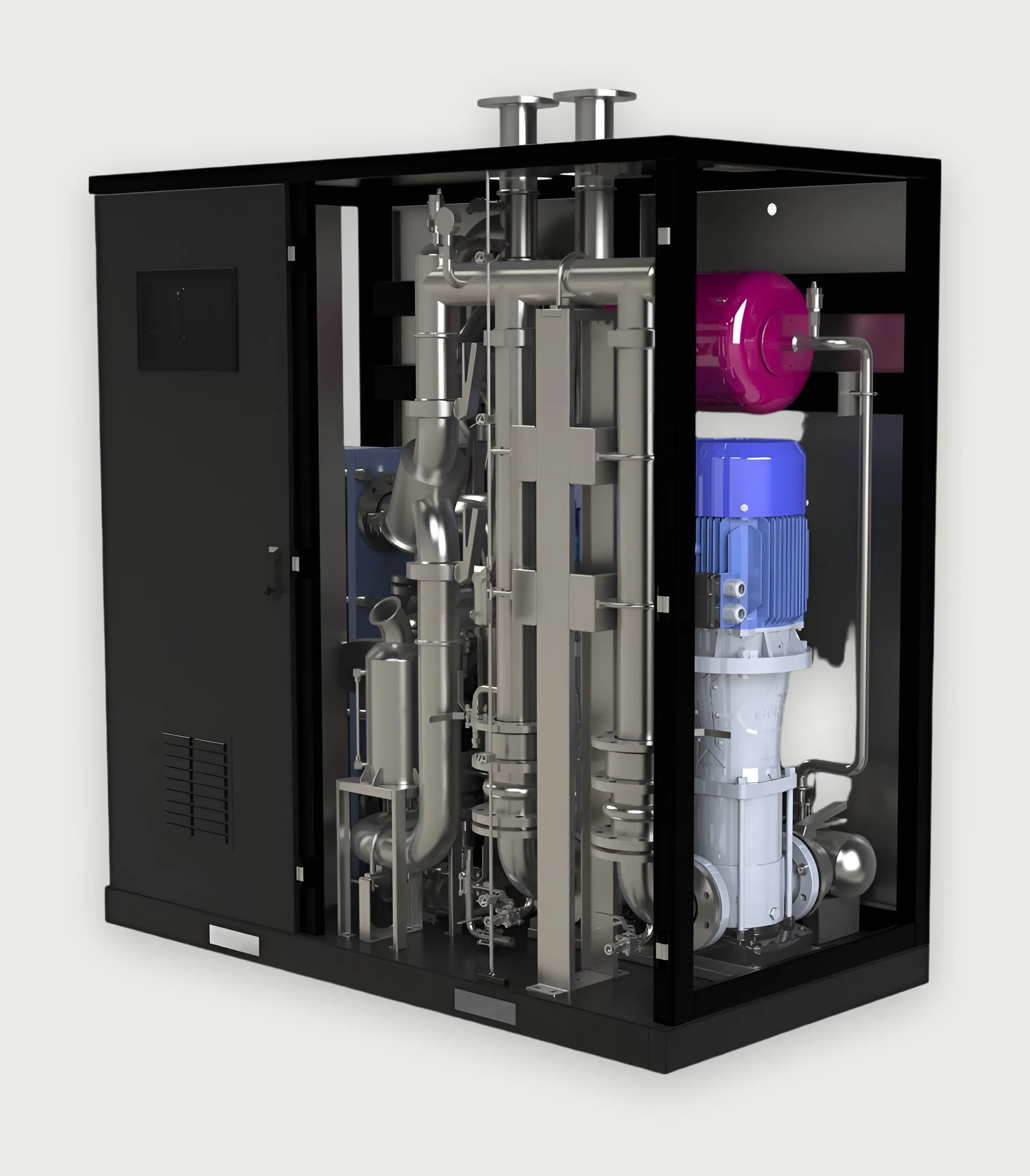
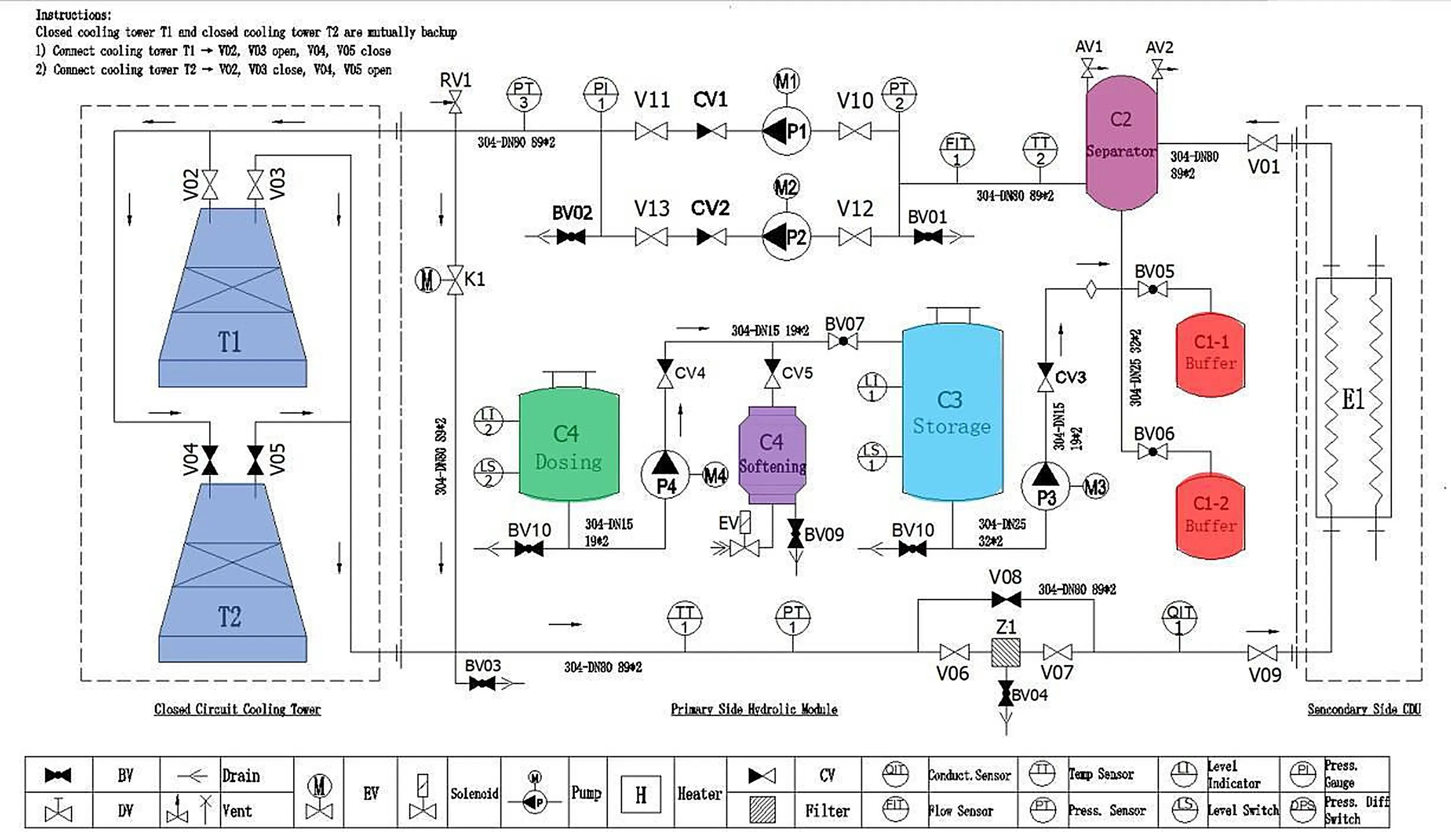
A plate heat exchanger separates the IT loop from facility water. Dual variable-speed pumps hold flow and pressure. Reference units: 500 kW and 2.5 MW.
View productPrimary loop
07 / 09 · Facility water system
LINKWAVE scope
Facility water carries heat from the CDUs to the heat-rejection plant. Water quality is managed by make-up, dosing and filtration on this side.
08 / 09 · Primary circulation
LINKWAVE scope
Skid-built pumps with variable-frequency drives, storage, make-up and dosing. 125 kW to 2.5 MW, 10–250 m³/h.
View product09 / 09 · Heat rejection
Interface
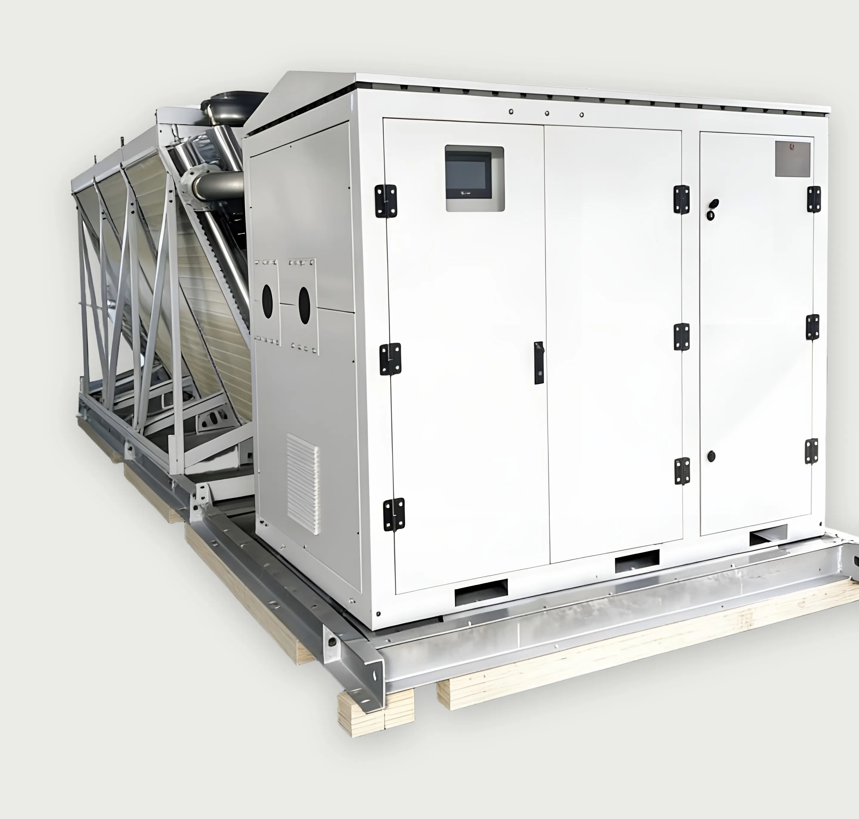
Three reference arrangements: isolated CDU with chilled water; isolated CDU with cooling tower and pump station; direct-connected CDU with dry cooler and online purification.
Heat travels from chip to heat rejection. Select a stage for detail.
Solutions
Scale
Rack
Rack CDU
Row
In-row CDU
Room
Centralized CDU
500 kW – 2.5 MW
Facility
Primary-side infrastructure
125 kW – 2.5 MW per station
Modular
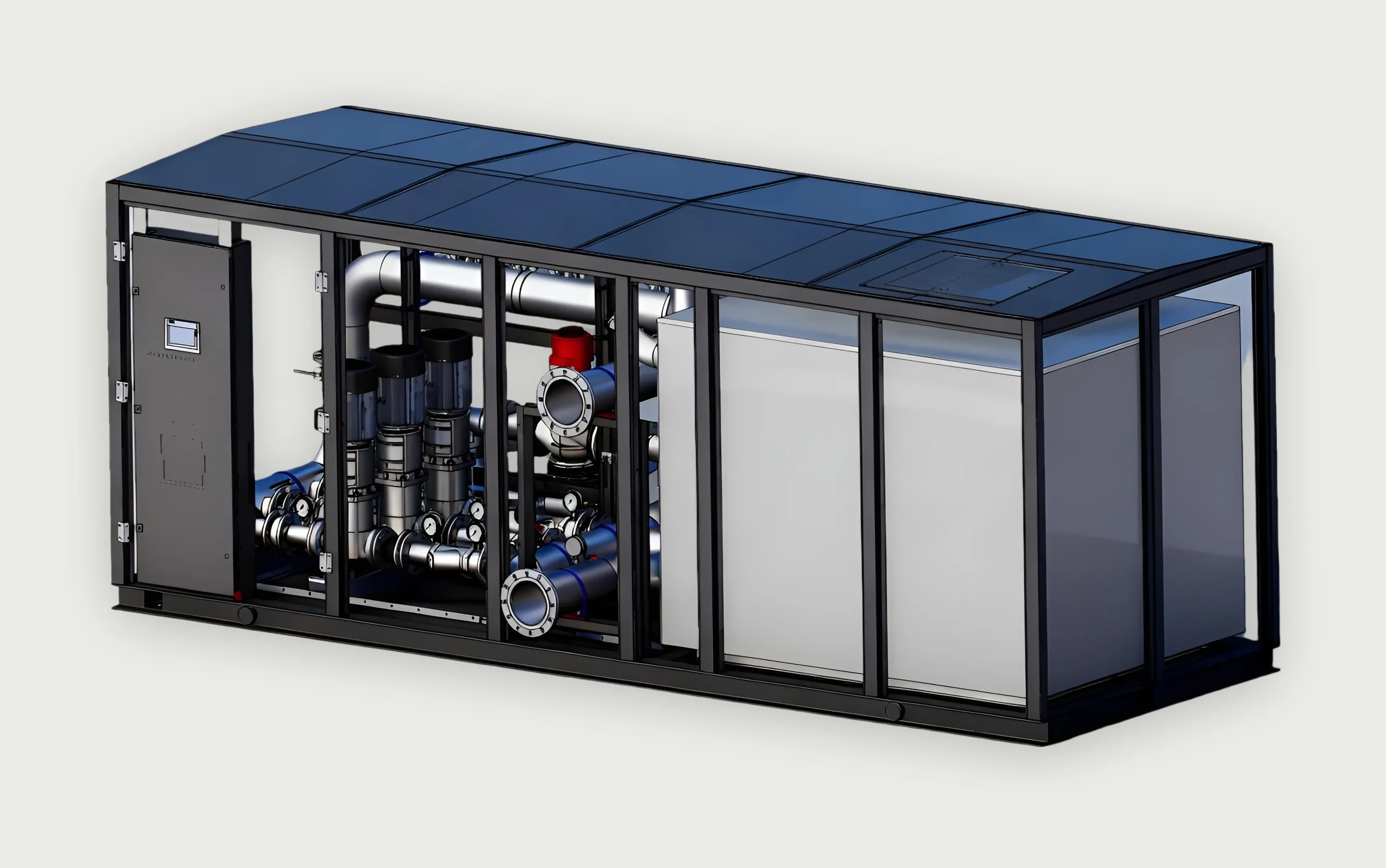
Prefabricated / containerized cooling
Outlines are schematic and not to scale.
Products
CDU systems
500 kW – 2.5 MW
Separates the secondary (IT) loop from the primary (facility) loop through a plate heat exchanger, and controls secondary flow, pressure and supply temperature.
Dual-pump, isolated design in cabinet and frame-mounted formats.
ExplorePrimary cooling
125 kW – 2.5 MW
Moves heat from the centralized CDUs to dry coolers, cooling towers or a chilled-water plant, and holds primary-loop temperature under changing load.
Variable-frequency pumping with closed-loop load feedback.
ExploreDistribution
Distributes secondary-loop coolant from the CDU along the aisle and into each rack, and returns it.
Sanitary-grade stainless steel, assembled without thread tape or sealant.
ExploreRacks
Houses the IT equipment and terminates the secondary loop at the server through an integrated rack manifold.
Manifold, hoses and switchgear integrated at the factory.
ExploreControls
Control cabinets and the operator interface are designed and built in-house for each system. Pumps and heat-rejection fans run on variable-frequency control, with Ethernet / Modbus communication available as an option.
Modular cooling
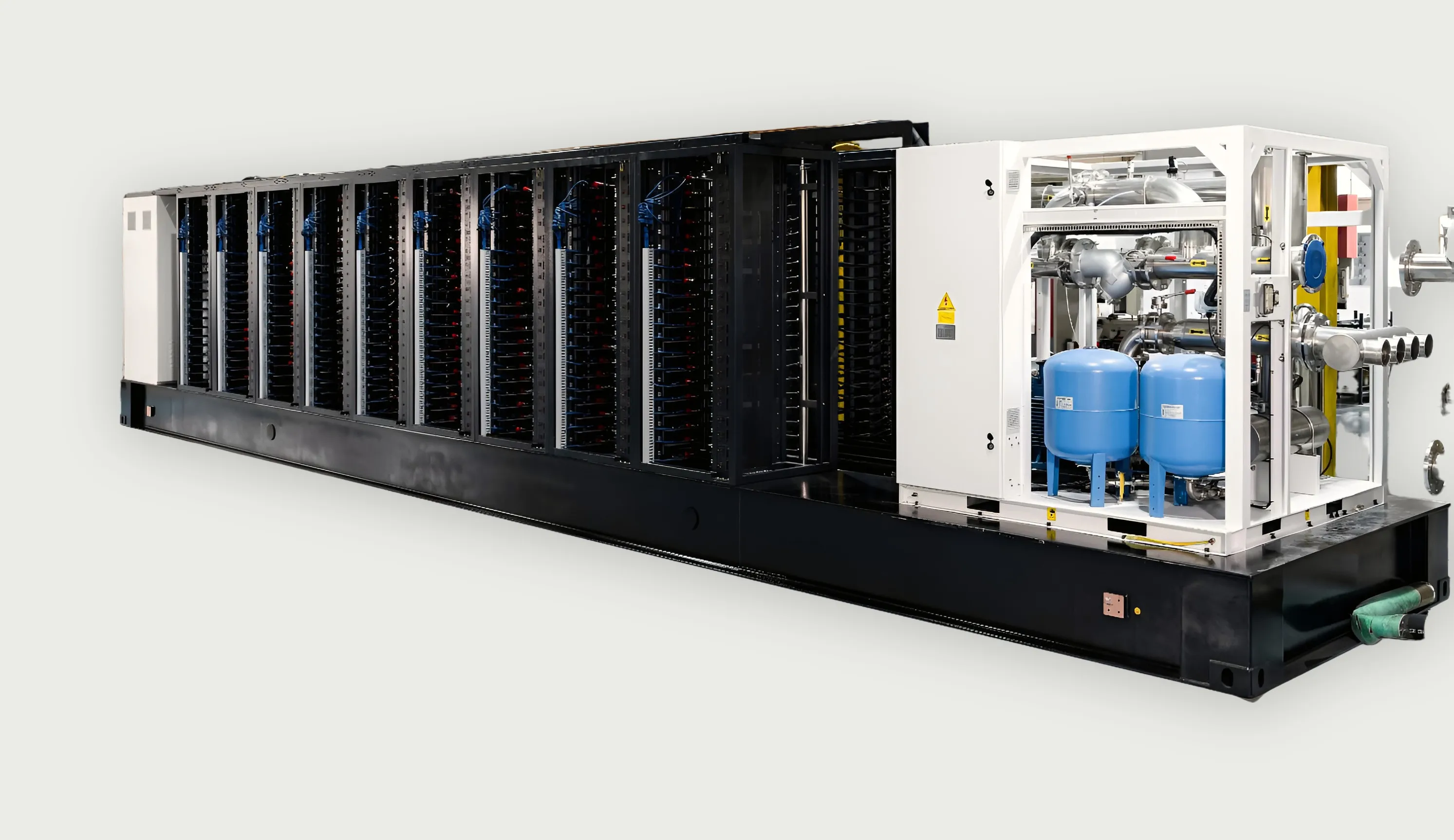
Prefabricated liquid-cooling infrastructure designed to reduce on-site integration complexity and support rapid deployment of high-density computing capacity.
United States / High-density computing
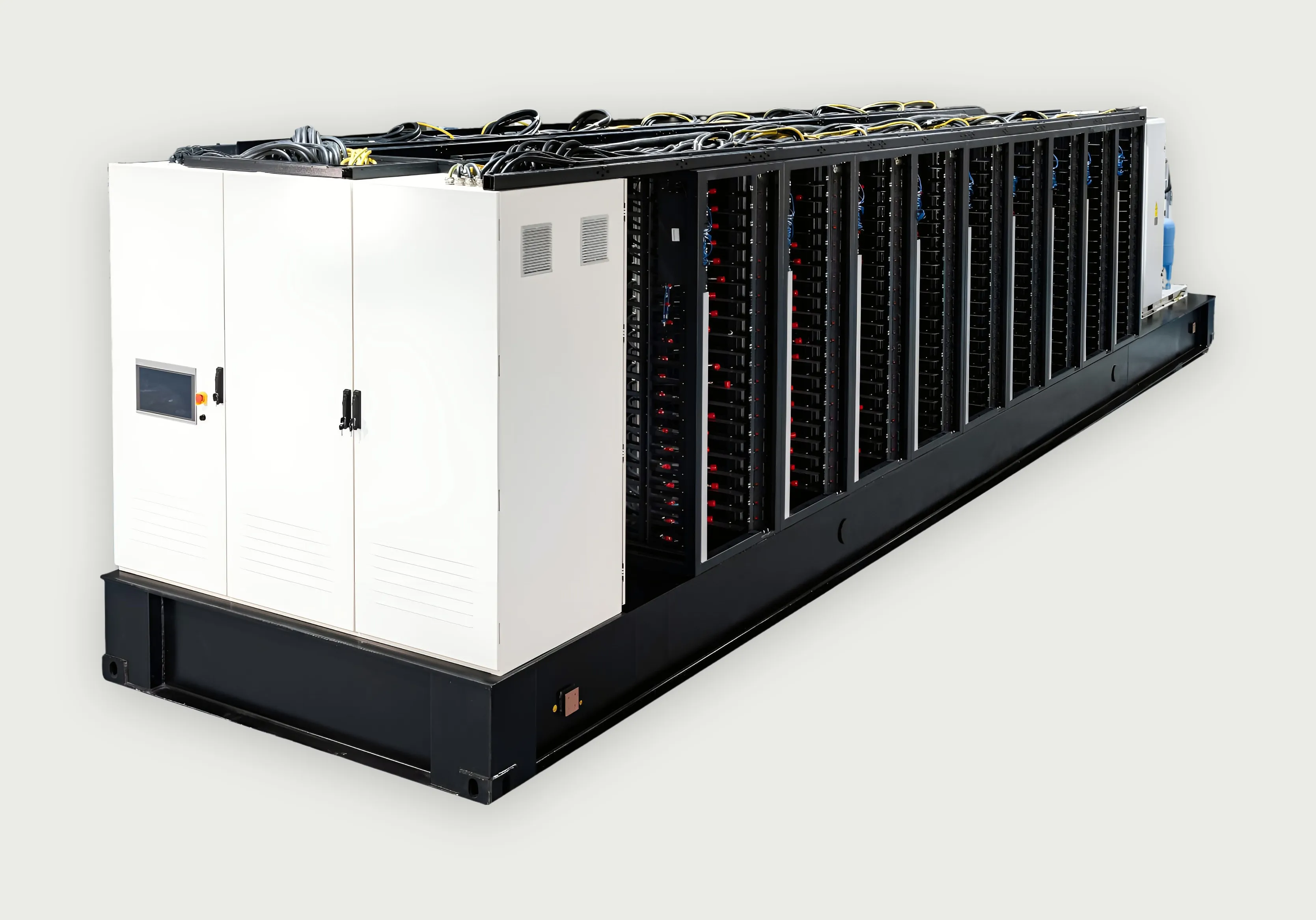
Twenty liquid-cooled racks, one centralized CDU, the piping network, switchgear and a dry cooler, integrated on a common base frame and delivered as one indoor system.
Field proven
Reliability is designed into the hydraulics: what can fail is duplicated, and what needs service can be reached without stopping flow.
Engineering
LINKWAVE engages before procurement. Bring a thermal load and a set of constraints, and the first output is a cooling architecture.
Pre-sales engineering package
Global deployment
Equipment delivered. No public project reference.
Equipment delivered. No public project reference.
Regions show where equipment has been delivered. They do not indicate LINKWAVE offices or service centers.
Bring us your thermal load, rack density, facility constraints or RFP. Our engineering team can help define the cooling architecture.


